Hi
Some years ago I converted my T6 pancake to a modern AC alternator, that should give 70 w. It produced plenty of power, but it had to work loose often due to vibrations. I feared that the vibrations should provoke damages to the timing mechanism so I skipped the system again, and had to search for another solution.
I learned from a friend how to replace a weak pancake magnets by more modern super magnets, that can be hidden behind the cover, and it works well. I have done this conversion to my B29 and the T6.
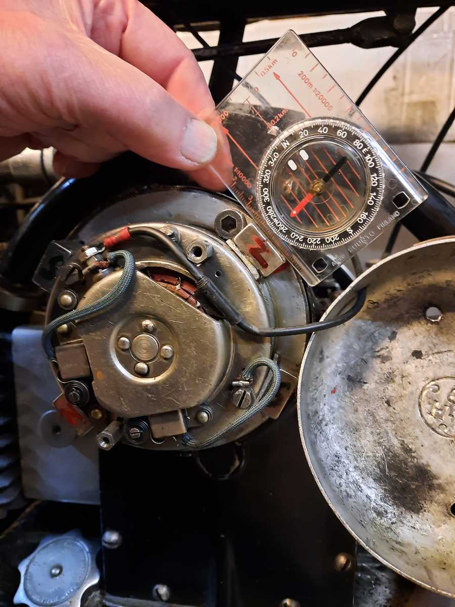
I use four Neodym block magnet, size 20x20x10 mm with the magnetic field perpendicular to flat areas, and when I place the North poles nearest to the two fastening screws, the dynamo produce negative earth (otherwise it produce positive earth). Due to the position of the fastening screws, the four magnets can not be placed at right angles to each others, but no matter it produces well anyway.
In various books i have seen, that the pancake typically produce 3 to 4 amps at app. 3000 RPM, and my hope was to reach that. As you can see from the test setup I had the pancake to give 4,15 amp at 6,21 V at a little below 3000 RPM. I also had it to produce 4,2 amps at 6,4 V and even more than that, but as I am not an expert on how heavy load the solderings, commutator and brushes can handle, I did place a piece of 1 mm alu sheet under each magnet to reduce magnetic flux. The figures I gave are with these alu underlayers. I have glued the magnets and underlayer to the steel areas in the pancake body with Araldite, but I have recently read that UHU MAX REPAIR glue should be the best. By the way, I used a handdrill that could run up to 3000 RPM in the test setup.
Be aware of that these magnets are very strong and you probably will end up with several carpenters louse (translated from danish) on your fingers, and when in position and the cover in place, it easily holds an 8 inch universal spanner.
In place of the cut-off relay, that itself steal 1 amp. or more, I use a diode. Those I have are well beyond what is needed (200 V / 25 A), but that was what the retired car electrian had in stock, an I got a handful very cheap
I also attach a copy of a wiring diagram from another thread in this forum, I have omitted the zener diode to regulate voltage to the battery, as I fear, that the dynamo then will produce max. power constantly to the frame when battery is full. Instead i have fittet a toggler switch in the power line from the daynamo so that I can switch of the load when I can hear when activating the horn, that the battery is full. But as I am no expert either in what happens inside the dynamo when running without load, I should be glad to hear comments on this.
I attach some photos
hoejmark

Screen snip of
wiring diagram.
 Original wiring diagram in Word (docx) format.Screen snip of wiring diagram added. Images converted to linked files to correct distorted display. Please see Taking photos with mobile/cell phone. - Dave, 02Feb2023

