Though applicable to all roller bearing connecting rods, these notes particularly apply to the very narrow, single-row roller, big ends. Typically used in the side valve engines from the EW onwards, they present some unique challenges to inspection and refurbishment.
The traditional method of inspection by passing two precision close fitting bars through the small and big end bores fails at the big end. Because it is so narrow in aspect relative to the diameter the big end bore does not provide a very good registration surface. The slight clearance required to slip the bar through would allow the bar to wiggle about such that any hope of an accurate alignment could be forgotten.
What is required is a mandrel with a flange that the side of the big end can be lightly clamped to. This does not even need be a close fit in the bore, indeed it is preferred that it is not. In this way it is ensured a worn or out of round bore is not throwing the mandrel out of truth. But the side of the rod, at least one side, needs to be flat. This should be checked against a precision surface plate, which will be required anyway for the next step.

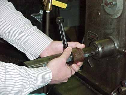
That is to check the rod for twist and parallelism of the eyes. The picture shows the setup with the mandrel clamped in place. If the small end bush is to be renewed it should be pressed out and a mandrel fitted directly into the rod. The reason is the bore though the bronze bush is often wonky due to hand reaming and other non-precise practices over the years involving worn bench vices, hammers, and drifts. There is no point in straightening the rod, only to find things are crooked again after renewing the bush. In this case the small end mandrel is a length of ground drill rod (silver-steel.)
You will need a matched set of parallels to check for twist, the goal is to touch the parallels simultaneously in four locations where the mandrels rest. That is, no rocking across diagonal points of contact. Corrective action is grabbing the big end in the bench vice and applying a large adjustable wrench to the I-beam just below the small end eye. Extra points are awarded for using a bit of aluminum shim to prevent the jaws of the wrench from bruising the rod. Do not use the mandrel, nor pass a tommy-bar through the eye, to apply the twist. You want to avoid any method that may stretch the eye out of round. Also make sure the big end is completely sunk down into the vice jaws so it is not party to the corrective ministrations. You want any twisting confined to the I-beam section between the eyes. Remember you want the side of the big end to stay perfectly flat.
The second test involves checking for parallelism between the eyes. There are special tools for this, but the same results can be had with a set of machinists inside micrometers if you are willing to spend a little extra time probing for the tightest point between the two mandrels. A typical set is seen in the background of the accompanying photo. Corrective action again is brutal, an arbor press is ideal but a mallet and bench vice can take you far. If using a press, again use aluminum at all points contacting the rod to avoid bruising and dents.
It will be found with dismay that little effort is required to deflect the rod. But all is not as bad as it seems; the piston contributes a lot to keeping side loads off the rod and keeping the rod true. Also the rods are very springy, a point that will make itself annoyingly felt as you try to make that last final correction only to over shoot the mark.
As to which to tackle first, twist or parallelism, go first for whatever is out of kilter the most. You will find that as you correct one, you will disturb the other. It becomes a battle of diminishing returns back and forth between the two. So how close is good enough? For twist, a slight perceptible rocking is perhaps unavoidable, but you should not be able to pass more than a 0.001 shim between a mandrel and parallel. This with the parallels spaced about four inches apart. You should measure about the same distance out on the mandrel from each side of the rod. The further out you measure the greater the sensitivity. But measuring out too far is just going to drive you nuts trying to correct to a level of precision that is not going to make an iota of difference to a mechanism that by definition, has to have gaps between the running parts to work. For parallelism, try to get the measurement within 0.002 on both sides. If this sounds like heresy to those whose scripture is Tuning for Speed and the like, I hasten to add there is a way to further improve these numbers to nigh perfect, more of which at the end.
So now you have a straight rod, or one nearly so as your patience will allow. Next is to have a round and true bore in the big end eye. Round meaning cylindrical and true meaning perpendicular to the side of the rod as used by the mandrel in the previous exercise. It helps to have the foresight to mark this side with a felt tip pen. Center pop marks and scribed lines are taboo. If the sides are perfectly parallel you can use either, but they are not always perfect. If the big end eye is out of round, and they invariably are, all it needs is (hopefully) a light lapping/honing. For most connecting rods this entails reciprocating the rod back and forth over a rotating lap/hone. But most rods usually have enough length to the bore to act as guidance and alignment for the honing process. The single-row roller big end is so narrow it does not. The rod will tilt back and forth as it is stoked to and fro causing the bore to be honed to an hourglass shape. What is needed is some way to hold the rod square to the hone at all times.
That method is to use a truing sleeve. These are supplied with the hone to true the stone(s) when replaced or when they wear unevenly. In this case a truing sleeve is required bored to the same size as the big end eye. It is unlikely the truing sleeve supplied with the hone will be the right size, but they are simple enough to make by boring a piece of heavy wall tubing and facing one end true. This last bit is the most important; the end must be dead square to the bore. If you have several rods to do, like a pair for your favorite horizontally opposed twin, start off with the bore the same as the smallest dimension you can measure on any of the big ends. This is usually perpendicular to the beam, as the eye tends to stretch oval in line with the axis of the rod.
I pondered long and deep as to how I could fasten the rod to the end of the truing sleeve, yet allow it to move about radial so the bores could self-align. Not having any good ideas, I decided to try just holding the two face to face while honing. I found it worked perfectly fine, even with honing oil flooding the action. The grip is shown in the accompanying photo.
The truing sleeve takes most of the torque; the rod has very little contact with the stones, especially at the beginning. Indeed it is just along for the ride so to speak. The bore in the truing sleeve also prevents the hone from being too aggressive and catching on the oval bore of the rod. If your pair of rods is closely matched, you should alternate between the two as you hone the big ends progressively larger. The truing sleeve bore will gradually become larger with the rods following suit.
Do not take out any more than required to true up the bore. If you have to go deeper than 0.005 into the surface, your surface hardness is going to start to drop off. This pertains to direct carburized surfaces; that is where the rollers run directly in the rods. Earlier rods, like in the EW and A31 have a press in race of bearing steel. (I think, I never had one sent out for a metallurgical test.) Proper bearing steel is virtually through hardening. However some manufacturers made their own bearing races in case hardened steel to economize, particularly the custom sizes and shapes (like Indian Motorcycle.) I am not certain, but some time about 1935 Douglas eliminated the separate bearing race and direct hardened the eye of the big end instead. The earlier type is prone to the races coming loose if the big end eye stretches. This will happen if high revolutions are indulged in to wring the utmost performance out of your little EW. That is if you do not break the crankshaft first.
The case hardening of the surface only extends about 0.040 deep, but the hardness drops off rapidly the deeper you go till you are down to the level of hardness residual in the core. Hence no deeper than 0.005 or the surface will be too soft to support a hardened roller. Remember that Douglas has already ground through some of the case. Standard eye diameter is Ø1.625 if you are well over that, your rod has already been reclaimed once and its number is up.
I tend to like the later rods, as there is no race to come loose. They are not as big on the outer diameter, a little less than the EW, but then they do not have to house and buttress a pressed in race. Since the originals tend to work loose, obviously they were not up to the job as originally designed.
As oversize rollers are getting practically impossible to purchase unless custom made, it probably will be simpler to renew the crank pin race with one made slightly oversize to suit so standard diameter rollers can still be used. But even standard Ø5/16x5/16 rollers in decent quality and precision (class G3 or better, +0/-3µ) are getting very difficult to buy. If anyone knows a source of Imperial size rollers NOT originating from the Indian subcontinent, please let the author know! The latter rods without the press in race used Ø1/4x5/16 rollers, with a larger crank pin race (though the crank pin itself was still Ø0.750.) By happy coincidence that it is a very common roller size used in the old Indian V-twin motorcycles since time immemorial. So they are readily available from the reproduction vendors and also still to be had ex-WD stock at the autojumbles in standard and in over-sizes.
Rather than use a larger (late) crank pin race in the earlier engine with the connecting rods having the press in race, it may be to ones advantage to instead make the rod race a smaller internal diameter than standard. This will make a race with a thicker radial wall that will be a bit stiffer and so, after honing the rod true, help prevent the rod eye going oval again. This is illustrated in the final of the above three images.
The previously mentioned sizes pertain to the 350cc machines (and no doubt the 250cc as well). But the same idea applies to re-roller-ing the 500, 600, and 750cc side valves.
Roller bearings need some clearance, miniscule as it may be. It is a mistake to set them up too tight, as though they may rotate reasonable friction free by hand, they will tend to run hot, prematurely shortening the roller life. The clearance is required as in a plain bearing to allow oil to separate contacting metal surfaces. While it is a rolling contact and not a sliding one you still need a little oil in there{1}. Rollers do skid part of the time, particularly those not in the direct load path. Probably more than we would like to know! There is quite a bit of feel to setting up a roller bearing, but for crank pins you probably can not go far wrong by having a total of 0.001 diametric clearance. That is the big end eye, minus two roller diameters, should still be 0.001 bigger than the crank pin race. This will allow a quarter of a thou between each roller and the surface of a bearing race. Still worried? Then take the whole assembly to someone experienced and do not gripe about the cost!
Now let us turn our attention to the small end. Bronze is the material of choice, even if they are sometimes called brasses. And when the old repair manuals say knock out the old ones, dont. Press them out. The usual course of action is to size the inner diameter of the bush so that when pressed in it collapses just a smidgen, then a light pass through with the hone or lap to fit the gudgeon pin. If you are using a hand expansion reamer to get it within honing/lapping range, then you left too much to take out. Hand expansion reamers are a good way to start down the path to a crooked bore and I strongly recommend not using them if you can avoid it. And they have to be really sharp, as bronze is an unforgiving alloy. Typical scenario is you keep adjusting the reamer trying to make it scrape out just a wee bit more and all of the sudden it will decide to make a cut to make up for the last three passes when nothing happened. Result: oversize hole.
By far the best way is to use a vertical milling machine and a boring head. Leave the bush 0.010 undersize so you have some material to bore out. The advantage of this is that if there is still a bit of twist or non-parallelism between the big and small ends, it can be taken care of when boring out the bush true. Setup is off the same side of the big end eye as used for the inspection mandrel. Naturally it has to be setup accurately if you want accurate results. I had concerns about the rod being cantilevered out from the big end, and racked my brain as to how I could snub the small end without deflecting it. I need not have worried. With a sharp tool and the slight amount of material to bore out, chatter was not a problem and I just snubbed the small end eye with my thumb and forefinger for good measure. The center to center distance between the eyes is not that critical, plus or minus 0.020 in the length of the rod is really not going to matter on a side valve engine. There is no need to measure off the big end a set distance. Which is good, as the work piece clamp will likely obscure the big end. Just indicate the existing bore of the small end bush. But pre-bore the bush so you have a reasonable inner diameter to indicate, and not a rough drilled hole that may have started to wander off center! If your boring head is not capable of boring to 0.0001, and few are, stop a half thou short and lap/hone the bush the final amount. Check the fit with oil (olive oil is particularly good) as a dry pin will stick and jam so giving a false impression that it is a tighter fit than it really is. You should be able to push the pin through with your thumb with some drag. If it drops out from its own weight, you are too loose, try again.
Note all this disturbance of the lower end, and the top end too, means that the piston is not going to stop in the same location up the bore. So if the bore has a ring ridge worn at the top, there is a good chance the piston will go a bit farther than it once may have and break the top compression ring on the ridge. So it is a good time for a re-bore, or at least take out the ridge with a ridge reamer (they do not work on blind cylinders.) The piston could alternately stop short, but the likelihood of that is inversely proportional to the damage and expense caused by it going too far!
{1} Oddly enough, too much oil can over heat a bearing as well. Having to churn the oil out of the way can turn bearing steel blue, by which point the hardness has been drawn out. Rolling element bearings are not meant to run flooded with oil.
© 2004 Douglas Kephart, Glen Mills, PA, USA


