Douglas,
There was a fair bit to digest in your last post!
No problem, get ready for some more indigestion!
The rocker inner tubes are a clearance fit between the perches
Ideally there should not be any clearance, it should be a snug fit. Maybe a thou or two clearance but even a sheet of newsprint as a feeler gauge would probably indicate too much. Fortunately unless the rockers seize and the sleeve has been rotating, there is no reason for the sleeve ends to wear into the perch. That there are no grooves cut into the perch (from sleeve or rocker arm) is a good sign; usually if they are it is the bottom that suffers the most. In this picture you can see the groove the rocker arm cut in the perch but towards the center where the sleeve is clamped it is the virgin surface.
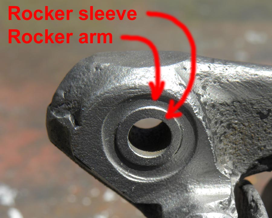
Even this is repairable by filling in with silicon bronze. The tricky bit is it is best milled flush (rather than filed) to make sure it is precise, square, and parallel to the opposing perch. Notice the owners file hash-marks to indicate valve position #3!

When they get this bad, one usually has to restore the length of the rocker arms too. (This set has non-standard pushrod tips, which were a feature of its competition history.)


Of course this undoes any heat treatment the rocker arm had, but sometimes a repaired rocker arm is better than no rocker arm. The tips for the valve stem and pushrod were case hardened, but I do not know exactly how deep. The bores do not seem to have been hardened at all. I dont think the ends faces were either as the ones I have tested seem soft. Admittedly those are ones that have been badly worn, and the good ones I am not about to attack with a file to see if they are hard! In this case, the valve pad and the pushrod socket were restored with Stelite, so annealing the original case hardening was a moot point. Ideally the rocker arms should have been re-heat treated to restore the core properties (assuming they are a 4-5% nickel alloy steel like the crankshaft and connecting rods are made of) but these have been welded about and reconstructed so much (entirely new pushrod tips) that the client decided it wasnt worth the bother. If they break (assuming the engine is ever started), then will just have to explore having all new rockers made.
In conjunction with that I re-profiled the valve pads, first to undercut for welding and then to machine the Stelite. For that it is handy to have a fixture to hold the rocker arms like this:


These rockers were in really bad shape, so I didnt really check how thick the case was. It was mostly gone, they were worn that bad! And the pushrod pockets looked like they have been re-machined with a blunt drill. Since I was roughing away with carbide tooling, any residual hardness was not noticeable though I got the impression it was only a skin about 0.020 inch thick at most at the valve pad. I probably do have some other junk rockers that I can grind back and check on the hardness tester if I get a spare moment. Where I did such on original connecting rod big end race I had to send the work out for micro hardness testing. Conventional testing with a diamond penetrator uses high loads (150kg for HRc) which give a false reading (too deep an impression) when done close to the edge of the sample. The conrods were only case hardened 0.030 inch deep. My circa 1940s Wilson hardness tester will do lighter loads (less than 150kg) for Rockwell, Vickers, and Brinell scales for when testing on thin samples (sheet metal), but lacks the sensitivity for micro harness testing or testing to within 0.005 inch of an edge. So it is not ideal for testing case depth.
The holes in the sides of the rocker arm were added by some tyro boy-racer to lighten the valve gear. It has nothing to do with the valve lifting mechanism. The latter is attached to the access plate under the magneto. See here:

Some rocker arms did have lugs for auxiliary extension springs between the two rocker arms, but the DT motors dont seem to have used that. They used duplex valve springs on the inlet, triple on the exhaust, and the auxiliary springs were at the base of the pushrods. The pushrod springs were the same part number as the 350EW inner valve springs! Your rockers have all been worked over to some extent or the other. Originally they would have been left in the as forged or stamped (to use the UK term) condition. So you would see the part numbers 8550 and 8551 and the arms would continue right around the body as a shallow rib. But as I said, most have been sanded smooth and polished by now and it is getting hard to find an original, unmolested set of rocker arms. Here is a pair that have never been machined:

Yep, as you figured out it takes a while for the heat to get to the rocker arm reservoirs and for the lubrication to start to flow. If you only run the engine less than ten minutes, the lube might not start flowing until after the engine stops! Later engines with the enclosed valve gear just had a grease fitting into the center hollow of the rocker arm spindle. Though a grease fitting, these too probably were fed with heavy oil. Unfortunately I dont know of any owners manual for these models existing that would give a clue as to how often Douglas suggested lubricating the spindles. Surely they could not have expected the owner to lube the spindles prior to starting the engine every time? Today, one would not be using the engine every day but on special events, so going around and doing all the lube points is not such a big deal. Better over lubed than under lubed.
As for the crankshaft, impossible for me to venture an assessment. I dont know the name of the firm, and even if I did I unlikely ever had any business with them (unless Alpha Bearings) to have formed an opinion based on experience. I cannot imagine there are any commercial firms that have experience on Douglas prewar ohv crankshafts (or any prewar Douglas crankshafts!) As you probably gathered, I do my own and dont trust anyone else! I think most folk that are still racing these old Dougie engines have learned how to rebuild their own crankshafts.
Some indicators for a competent job would be did they provide an assessment or documentation of the components? Ideally photos of the crankpin or conrod surfaces showing any issues, or hopefully pristine surfaces? Did they measure and document how round the crankpins were? They do wear oval. Did they indicate the crank to see if it was bent? Was it crack checked? Lack of documentation would worry me. Also previously mentioned is checking the big end cages for square. A bent crank and/or bent cages can cause damage to the center web like this:

This crank came out of one of the late Bill Dent's sprinter engines, so apparently he didn't check his cages either!
Murphy s Law mandates it will always damage the component that is the most expensive and/or difficult to repair. Never the more easily repairable or replaceable counterweight, oh certainly not! Even this damage is repairable, though it is a risky job.
Once it is assembled, all this is hidden. You can try for perceived feel for radial clearance, but that is hard to do and the ability of the rod to rock from side to side can obscure any pure radial clearance. One thing you can check after the fact is the side clearance of the rod. If the sides of the rod are not worn and the counterweights are the original and returned to their original places the setting should not in theory have changed. The counterweights are marked T and F for which side they belong, and a match number that should correspond to that on the crank center web. If you go around the side of the conrod bigend with a feeler gauge and get a variable side clearance or too much that is an indicator they were not paying attention to the details.
As you would have saw in the post on crank assembly, the counterweights key into a groove on the haunch of the throw and the other end is locked by a tapered cotter. That means the lateral position of each counterweight and throw will vary a little and the side clearance of the conrod with it. Hence marking the counterweights so they are always returned to the original fitted position. Now decades later when you mix and match parts or of the crank has been bent and straightened, all that goes out the window. So the best practice is to skim the face of the center web square (it is a case hardened surface) and face the counterweight
in-situ to the correct distance. That does require a fixture to offset the throws in the lathe, and a tool holder to reach in where the conrod would be.

It is fairly easy to build up the counterweight lip with something like Stelite (the original counterweights were, oddly, not hardened in any way) so that you have extra material to machine to size.

I have come across cases where the counterweight was machined to final thickness in the mill. Unfortunately the back face of the counterweight (lying on the machine table) is not always square to the crankshaft, it is how it registers in the groove and the tapered cotter that determines how square it sits. Hence it is better to finish machine the counterweight thrust surface on the crankshaft in the lathe.
I do not like the original cotters. They are too soft in my opinion and ones I have removed show serious galling from the much harder crankshaft. They have to be soft so the tail can be swelled by riveting over. I have several issues with this. If the cotter galls it might seem tight because it is binding before it has really wedged the counterweight tight. If the counterweight is not tight, it will work loose. Not maybe, just a matter of when. The cotters should never be reused, but people do. The high spots from galling get dressed down with a file but that leaves the low spots. On re-installation the cotter goes in until it hits the ramp at the end of the depression and gives a false impression of how tight it is. Nor is the pressure spread evenly over the whole facet of the cotter. Lastly, in riveting the end over, one has to be careful you are not driving the cotter back out of the hole. Nor will it ever be a good rivet job as the tail of the cotter is not even a full cylinder, so it is never going to fill up the hole. Removing the cotters usually entails grinding the tail off (which hopefully precludes using it over!) and driving it out. The ends still in the hole usually are slightly swelled, so that has to be driven back through the hole. Nor are the holes through the counterweight square. They are usually curved because the reamer (or drill) deflected into the opening for the throw. This is not entirely such a bad thing, as the cotter only need bear against the hole directly opposite the point of pressure created by the v-notch in the throw. I do take a round pillar file and straighten the center half inch of the hole so that it does have a good bearing for the cotter. The rest of the hole does not actually matter that much.
I make new cotters from air hardening tool steel. Same alloy and hardened and tempered same as I would use for a cold chisel. I straighten the center of the counterweight hole as described above and take an oil stone and polish the face of the cotter and the vee-grove in the crankshaft if they are in anyway rough. Obviously the tails cannot be riveted over, so I paint of film of Loctite on the backside of the cotter (the cylindrical side) and they stay put. I drive the cotters in until the assembly rings, indicating the cotters are truly tight and seated solid. You tend to just get a dull sound with the original, soft cotters. Making cotters requires a fixture, of course!

The first facet is easy as you just need an inclined plane. It is when you get to the second facet you realize you have to clamp on something that is no longer parallel! Hence the removable stuffer/jaw/packing plate with a mating taper. You end up making three cotters. The first is a trial cotter that you drive in and see how much (or little) tail is sticking out of the counterweight. Then you adjust the depth of cut for the other two. It is not practical to go back and cut more off once the facets are machined (work holding issues); easier just to mill another pin. Hence making a test cotter for sizing purposes. I suppose you could sand the faces to take a little more off, but if you do not sand exactly the same amount off of both faces the centering of the cotter will change and shift/tilt the counterweight slightly, altering the side clearance on the conrod. Also if the facets are not square, they will not be a good seat against the vee-notch. So I machine them, where I know exactly how much is being removed and fixture ensures the angle and squareness. Both cotters never end up machined identical, so I mark the cotters T and F, like the counterweights are.
One should not rely on the cotter entirely to hold the counterweight. The counterweights should be a snug fit on the throws prior to installing the cotters. Tapping them on and into place with a mallet is ideal. Again, with mix and match parts sometimes the counterweight slips on too easily or even rattles when in place. If it is loose, it will eventually loosen the cotter, no matter what type it is. It is perfectly acceptable to pinch the counterweights slightly in a vice so they are tight on the throws. Better yet is to pinch the opening ever so slightly smaller and them skim the opening in the milling machine for a nice precision fit on the flat sides of the throws. The surface does not have to clean up 100%, just enough to give a good bearing surface to stop the throw from shuffling about. Again, if you can install the counterweights by hand without resorting to a few modest taps from a rawhide mallet, they are probably too loose.
While the Douglas crank assembly is not rocket science, it is not like rebuilding the bottom end of your BSA. Also to do a good job does require making a few fixtures/tooling.
Oh, and I was just reminded by looking at a picture there actually are four segments to the crankcase joint gasket.

-Doug


